Summary
Our approach is looking to reveal the findings only based on the DOS executable that can be downloaded from https://www.dosgamesarchive.com/file/mario-and-luigi/marioandluigi/. The source code of the game is also available at https://www.dosgamesarchive.com/file/mario-and-luigi/mariosrc/. The game was written in Pascal, and we’ll explain the DOS interrupts and the relevant instructions/functions that could be identified.
Technical analysis
The executable can’t run on a Windows 10 machine, and it needs to be emulated using an emulator such as DOSBox:
 Figure 1
We were surprised to find out that the game was packed using a well-known packer called UPX:
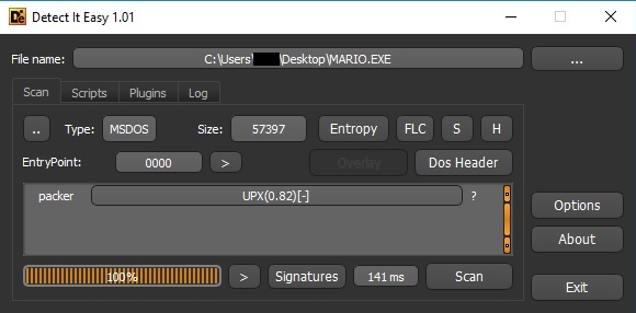 Figure 2
We’ve decompressed the file using old versions of UPX as well as newer versions. Unfortunately, after unpacking the executable, the new file couldn’t be emulated using DOSBox because it raises the “Runtime error 201” range check error in Pascal:
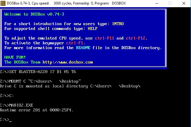 Figure 3
DOSBox has a basic debugger that can be used to debug the initial packed executable; however, the functionality isn’t comparable with x32dbg/Ollydbg (it’s more like gdb in Linux). Because of this limitation, we’ve decided to perform a detailed static analysis on the decompressed executable using IDA Pro.
As we can see below, the assignment operator is used to store the number of players in an array:
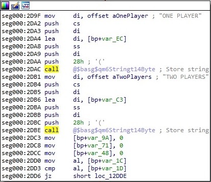 Figure 4
The menu items appearing on the screen at the beginning of the game are also stored in an array using the same operator:
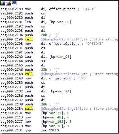 Figure 5
There is always the option to enable or disable the sound in the game, as highlighted below:
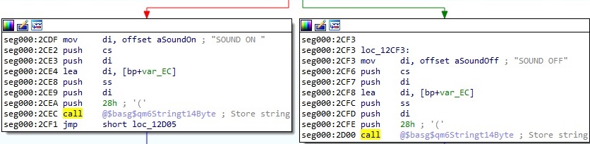 Figure 6
The status line option can be set to OFF or ON in the settings dialog:
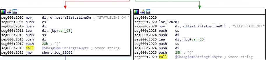 Figure 7
Players have the option to save the game progress, as displayed in the figure below:
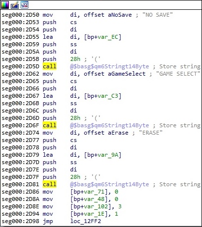 Figure 8
The final score will be concatenated with the “TOTAL SCORE:” string using the Concat function and then displayed at the end of the game:
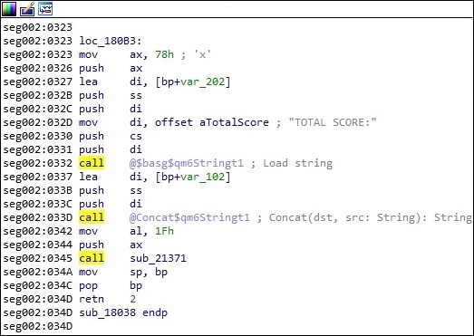 Figure 9
Players can pause the game at any point by pressing the P key:
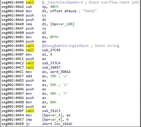 Figure 10
The MemAvail function is utilized to retrieve the size, in bytes, of the free heap memory. The result is stored in the DX:AX registers (keep in mind that the architecture should be 16-bit, so AX and DX are 16-bit registers). Whether DX < 0, then the program displays “Not enough memory” to the output:
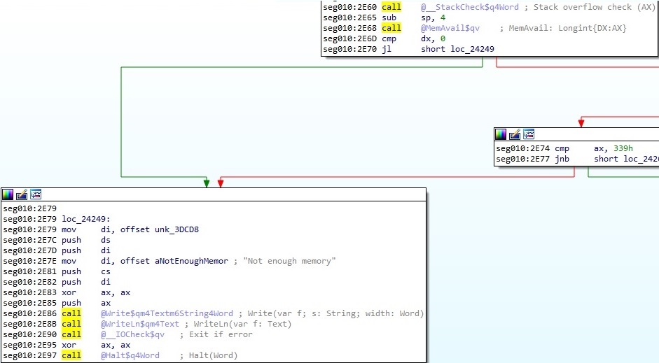 Figure 11
The current level number is concatenated with the “LEVEL ” string and then displayed on the screen:
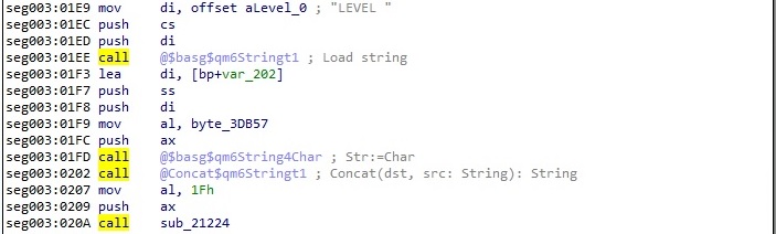 Figure 12
“GAME OVER” is displayed at the end of a lost game, and no lives are left:
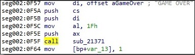 Figure 13
Using the int 10h (int 16) interrupt routine with AH = 0x1A and AL = 0x00, the program reads the display combination code. Whether the result stored in AL is 0x1A, VGA is supported; otherwise, it displays an error message using the Write function:
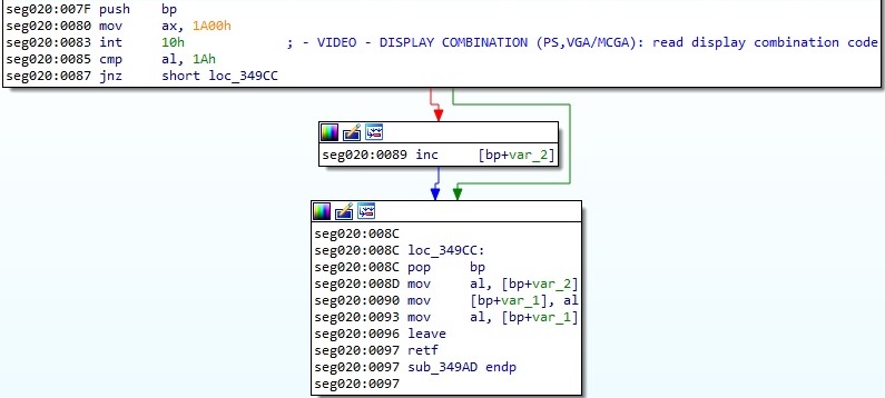 Figure 14
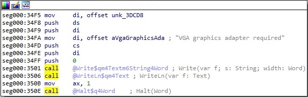 Figure 15
Mario & Luigi can be played with a joystick by running the DOS executable with the “-j” parameter, as highlighted below:
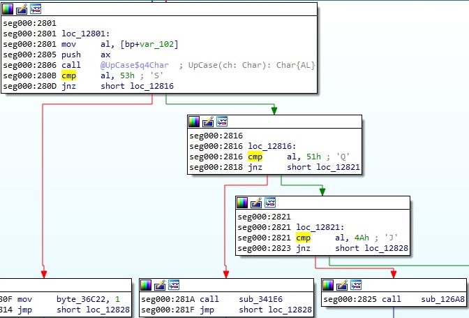 Figure 16
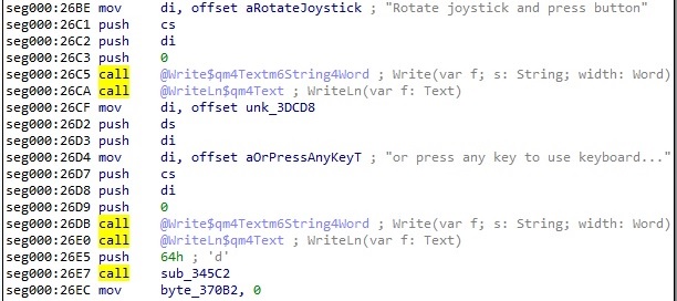 Figure 17
The int 10h interrupt routine with AH = 0xF is utilized to retrieve the current video mode:
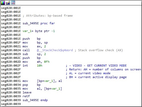 Figure 18
The video mode is set to Mode 13h, which is the standard 256-color mode on VGA graphics hardware (a resolution of 320×200 pixels):
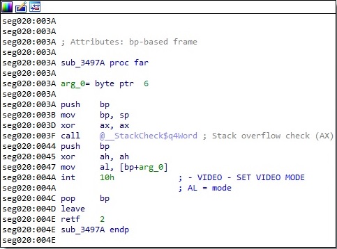 Figure 19
The game uses the int 10h interrupt routine with AH = 0x2 in order to set the cursor position on the screen:
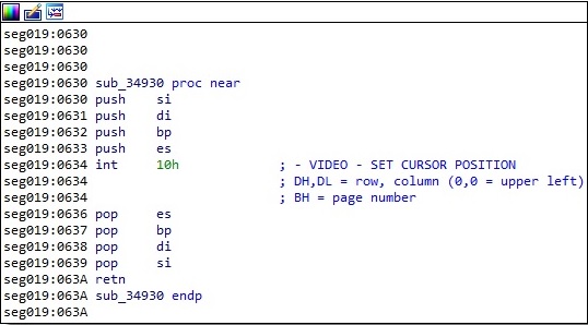 Figure 20
The same function from above is used multiple times with different register values. The program scrolls up the window by setting the AH register to 0x6 and BH, CX, and DX at runtime:
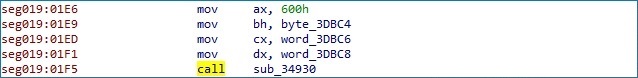 Figure 21
The program reads a character and attribute at the cursor position by setting the AH register to 0x8:
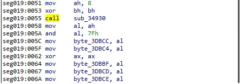 Figure 22
The 8×8 character font is loaded using the int 10h interrupt routine with AH = 0x11 and AL = 0x12. The executable obtains font information by setting the AL register to 0x30:
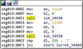 Figure 23
The cursor size is modified using the same interrupt routine with AH = 0x01:
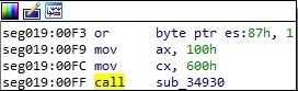 Figure 24
The program selects an alternative EGA Print Screen routine using the same interrupt routine with AH = 0x12 and BL = 0x20:
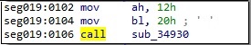 Figure 25
It displays characters at the cursor position using the same interrupt routine with AH = 0x09:
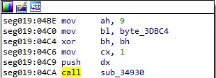 Figure 26
The executable writes a character at the cursor position and advances the cursor using the int 10h interrupt routine with AH=0x0E:
 Figure 27
The cursor position and shape can be obtained by setting the AH register to 0x03:
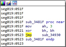 Figure 28
The DOS executable checks to see if there is any character available in the keyboard buffer using the int 16h interrupt routine with AH = 0x01:
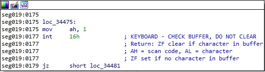 Figure 29
The next character from the keyboard buffer is extracted by setting the AH register to 0x00. Whether no characters are available, the routine waits until one will be:
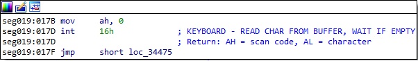 Figure 30
The int 21h interrupt routine with AH = 0x2C is utilized to retrieve the current time. The result will be used in the Randomize library function:
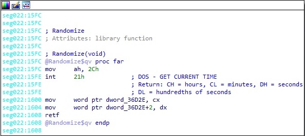 Figure 31
The program can close a file specified by the BX register using the same interrupt routine with AH = 0x3E:
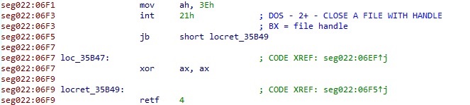 Figure 32
The program can create a file whose name is stored in the DS:DX registers by setting the AH register to 0x3C:
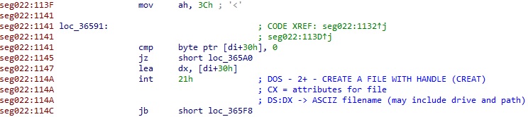 Figure 33
The verify flag specifying whether all disk writes should be verified after writing, is extracted by setting AH = 0x54:
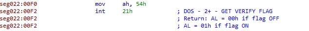 Figure 34
The executable extracts device information using the same interrupt routine with AH = 0x44 and AL = 0x00:
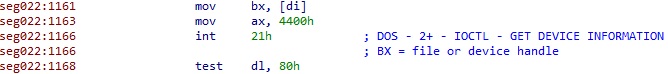 Figure 35
The current file position for a file specified by the BX register can be modified by setting the AH register to 0x42:
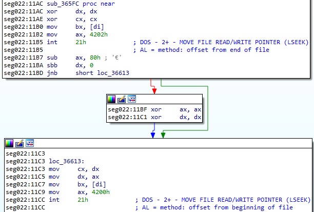 Figure 36
The program terminates its execution using the same interrupt routine with AH = 0x4C:
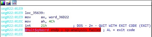 Figure 37
The DOS executable can read data from a file or device by setting the AH register to 0x3F:
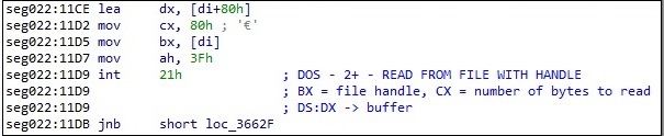 Figure 38
The DOS executable can write data to a file or device by setting the AH register to 0x40:
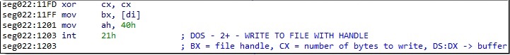 Figure 39
The program writes a character to the standard output using the int 21h interrupt routine with AH = 0x06:
 Figure 40
The Ctrl-Break interrupt handler is modified using the int 21h interrupt routine with AH = 0x25:
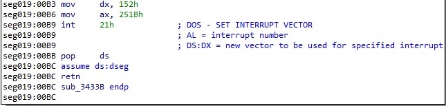 Figure 41
The program reads a byte from the interrupt mask register using the IN instruction:
![]() Figure 42
Figure 42
A byte from the keyboard buffer can be read using the same instruction as above:
![]() Figure 43
Figure 43
The executable turns the speaker on using the following instructions:
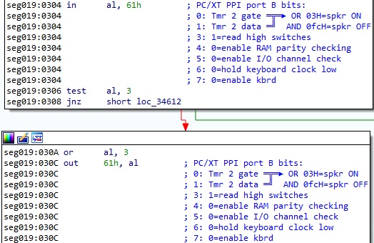 Figure 44
The speaker can be turned off using similar instructions:
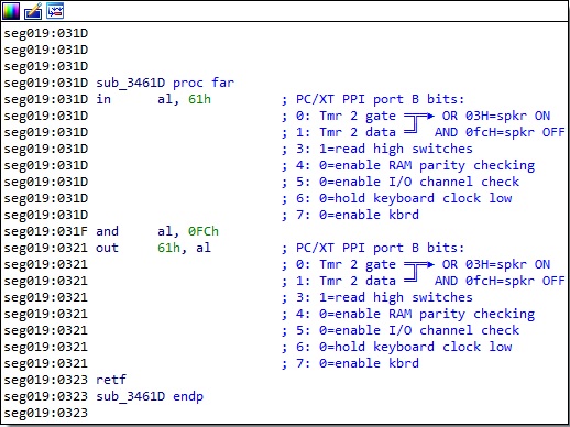 Figure 45
The DOS executable reads the 6845 index port and then reads data using the IN instruction:
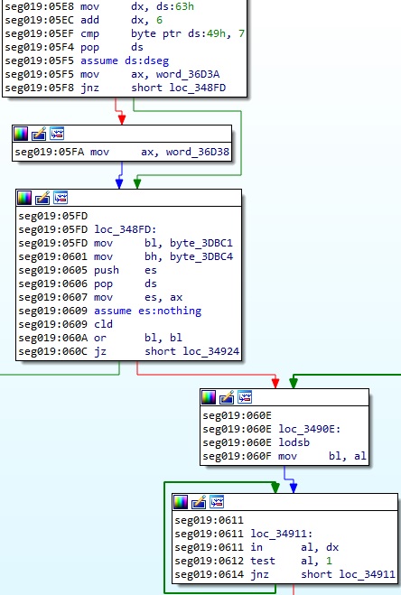 Figure 46
The program reads a value from the VGA status register using the IN instruction:
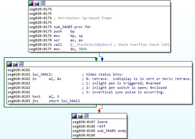 Figure 47
The executable moves the sequencer address register 0x3C4 to DX, and then it sets the memory mode:
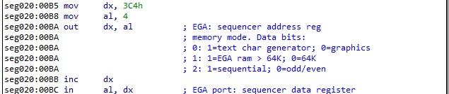 Figure 48
The executable selects the graphics controller registers 0x3CE, and then it sets the mode register:
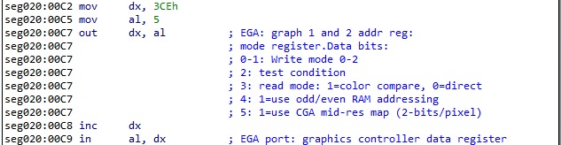 Figure 49
The program reads the CRT controller register 0x3D4, and then it accesses the underline location register:
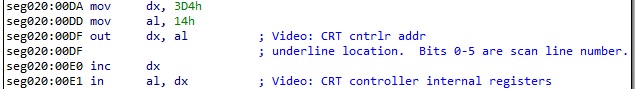 Figure 50
A byte from the Game/Joystick I/O port 0x201 can be read using the IN instruction:
 Figure 51
The DOS executable suspends/enables the interrupts, gets the 8259 end-of-interrupt value, and sends it to the 8259 interrupt controller using the following commands:
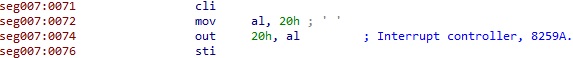 Figure 52
The following instructions can be used to disable all external interrupts except the system timer interrupt:
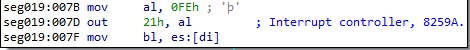 Figure 53
The program generates sound in the game utilizing OUT instructions, as highlighted below:
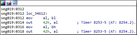 Figure 54
Before running the above instructions, the executable sends a control byte (10110110b) to port 43h:
![]() Figure 55
Figure 55
The LED bits can be modified by sending a byte to port 60h, which updates the LEDs on the keyboard. The Capslock LED, Numlock LED, and Scroll lock LED are set to off:
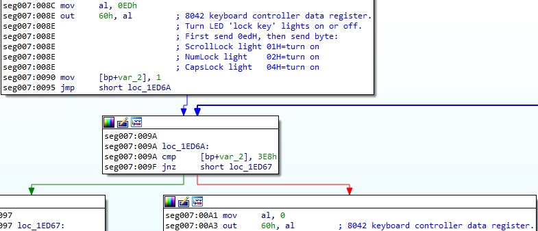 Figure 56
The game verifies if a key is pressed or not using the following commands:
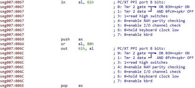 Figure 57
The program sets up a VGA color palette by sending the color number to port 3C8h and the red intensity, green intensity, and blue intensity to port 3C9h:
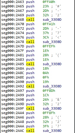 Figure 58
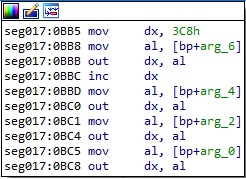 Figure 59
The DOS executable sends bytes to 6845 index port using the following instructions:
![]() Figure 60
Figure 60
It reads the original value from the sequencer data register 0x3C5, turns off chain 4 (bit 3), turns off odd/even (bit 2), and writes the new value back to the register:
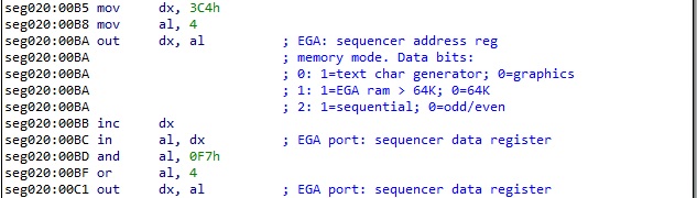 Figure 61
The file reads the original value from the graphics controller data register 0x3CF, turns off odd/even (bit 4), and writes the new value back to the register:
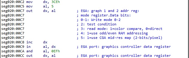 Figure 62
The program reads the original value from the CRT controller internal registers 0x3D5, turns off doubleword (bit 6), and writes the new value back to the register:
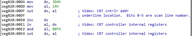 Figure 63
The Palette registers [0:F] are used to map text attributes or pixel color input values to the 256 possible colors available:
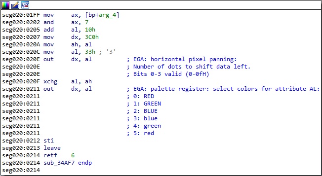 Figure 64
The DOS executable triggers the timer chip by writing any value to Game I/O port 201h:
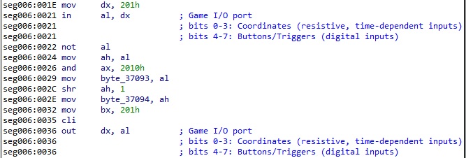 Figure 65
The executable allocates new memory on the heap by calling the GetMem function:
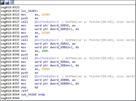 Figure 66
The interrupt vector can be retrieved and then modified using the GetIntVec and SetIntVec routines:
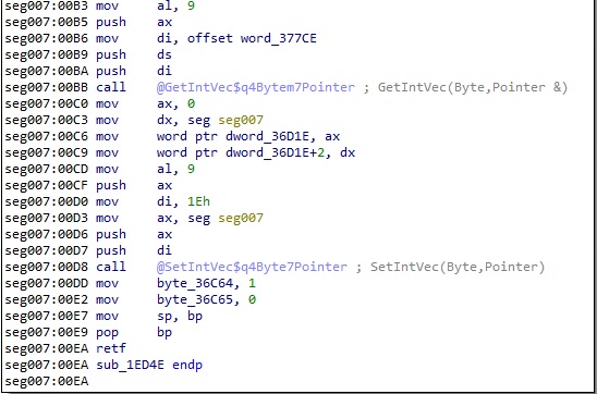 Figure 67
The program extracts the number of command-line parameters by calling the ParamCount function:
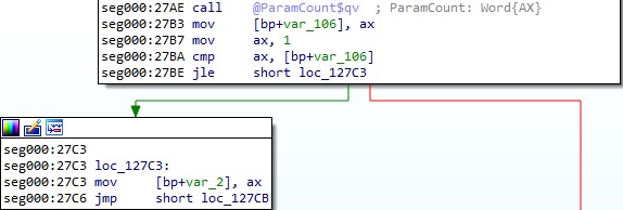 Figure 68
The values of the command-line arguments can be retrieved using the ParamStr routine:
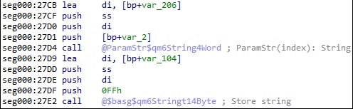 Figure 69
The DOS version can be extracted using the int 21h interrupt routine with AH = 0x30. The DOS major version is compared with 3:
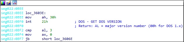 Figure 70
References
https://www.freepascal.org/docs-html/rtl/
http://spike.scu.edu.au/~barry/interrupts.html
http://vitaly_filatov.tripod.com/ng/asm/
https://www.plantation-productions.com/Webster/www.artofasm.com/DOS/
http://soooh.com/book/delphi/%E7%AA%97%E4%BD%93/MODE-X%20%E4%BF%A1%E6%81%AF.HTM
https://01.org/sites/default/files/documentation/snb_ihd_os_vol3_part1_0.pdf
http://copleyservices.com/SM3110_Technical_Reference.pdf
Article Link: Reverse Engineering an old Mario & Luigi game for fun – CYBER GEEKS